

01
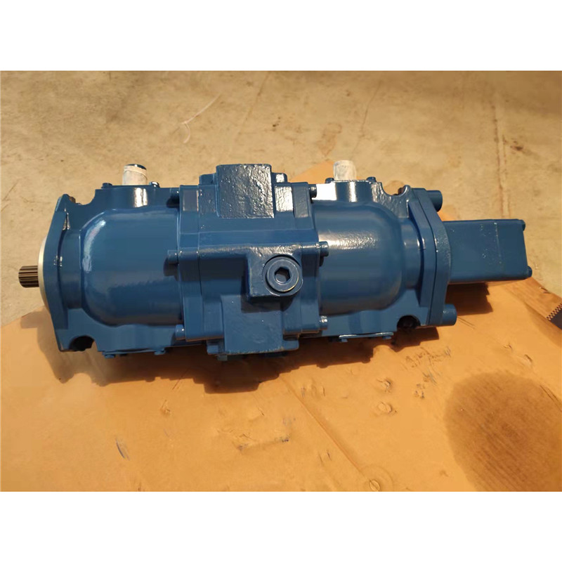

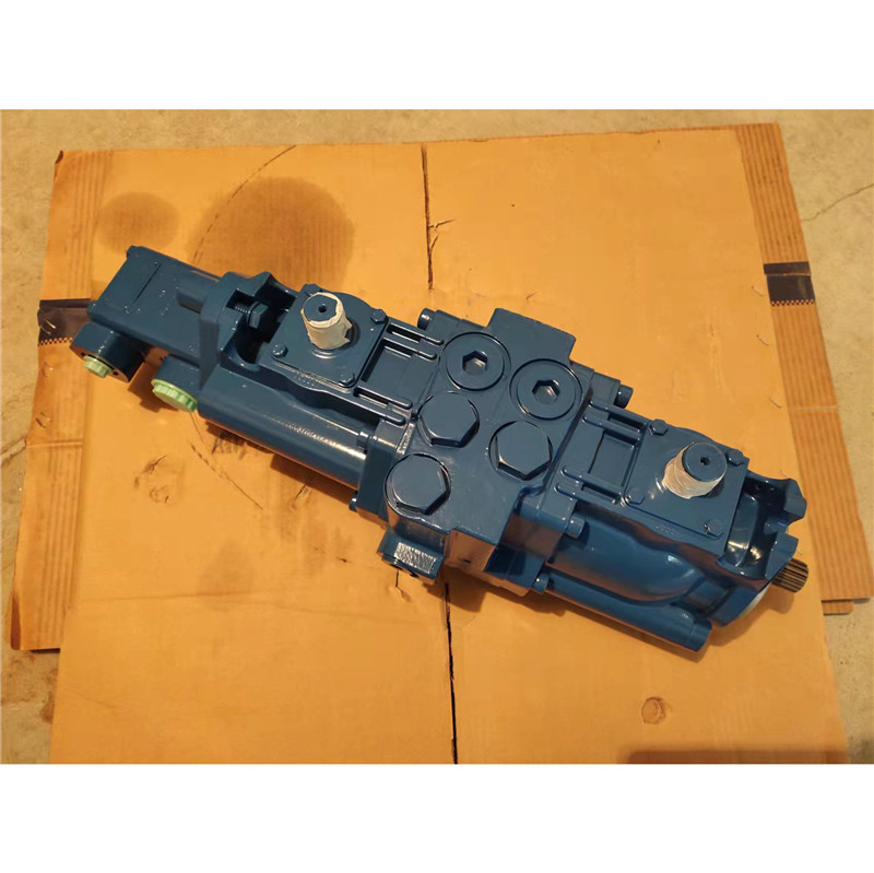
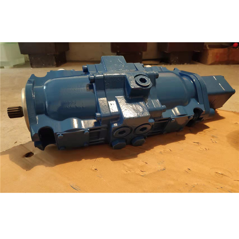
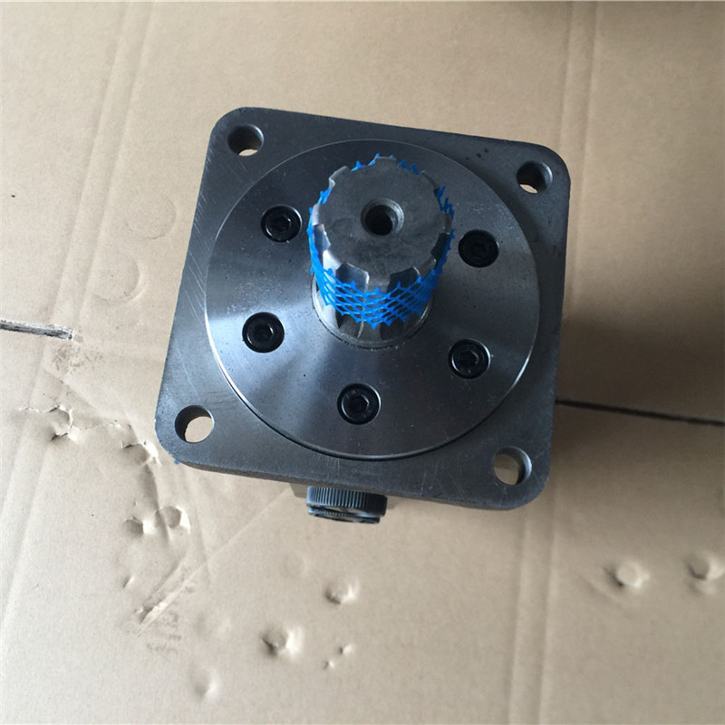
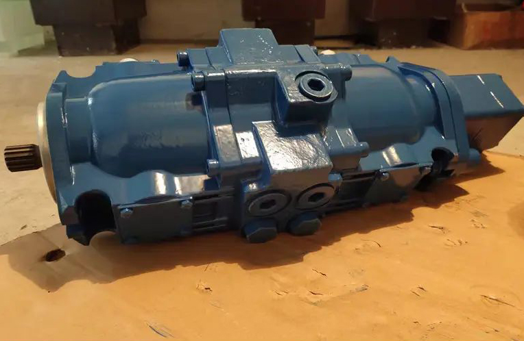
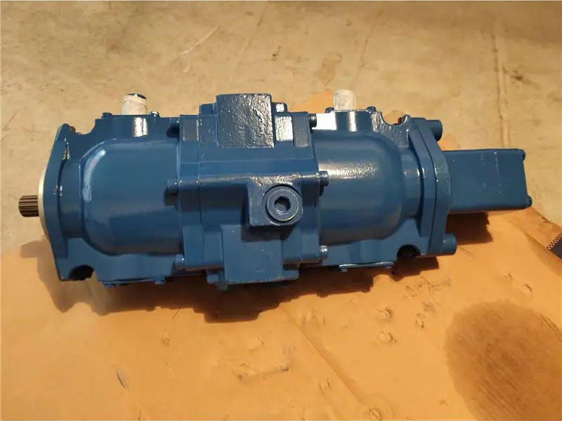
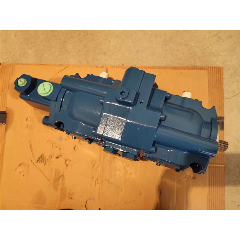
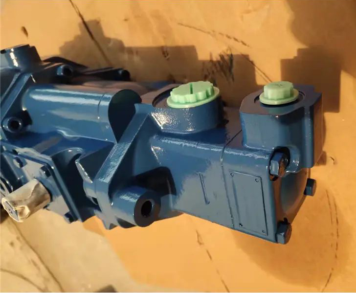
Vickers Variable Displacement Piston Pumps TA1919 series
The split-system configuration of Vickers 19 Series transmissions provides optimum application and installation freedom for the vehicle designer. The variable displacement, axial piston transmission pump is available as a single unit, or as a double unit designed for use with two independent motors.
Closed-loop replenishing check valves and a supercharge relief valve are built into the transmission pumps. Integral cross-port high pressure relief valves are also included when required. The only components needed to complete the transmission system are a reservoir, filter, heat exchanger and connecting lines. If an auxiliary vane pump is used, depending on its application, an external pressure relief valve may be required for pump protection.
Auxiliary vane pumps (single or double) can be provided with a cover containing either a flow control or priority valve, and a relief valve to protect the pump. From total vane pump delivery, the priority or flow control valve directs a controlled, essentially constant volume of fluid to the auxiliary circuit. From the auxiliary circuit, this flow goes to the supercharge circuit. Delivery in excess of the controlled flow goes directly to the supercharge circuit.
When the relief valve in the priority valve cover opens, controlled flow is diverted to tank. Excess delivery continues directly to the supercharge circuit. When the relief valve in the flow control cover opens, all pump delivery goes to the supercharge circuit. controlled flow rates and relief valve settings are shown in model codes on following pages.
The single auxiliary pump on the TA1919 double transmission pump is available with a flow divider valve in its cover for auxiliary circuits employing single acting cylinders. The valve directs a fixed percentage of pump delivery to the auxiliary circuit. From the auxiliary circuit, this flow goes to the supercharge circuit. The balance of vane pump delivery is continuously directed to the supercharge circuit.
Circuit diagrams of the various main and auxiliary pump combinations are shown on following pages.


Max. Intermittent Pressure 5000 psi
Max. Continuous Pressure 3000 psi
Rated Horsepower 22.5 hp per 1000 rpm
Fluid Per Fluid Recommendation Sheet M-2950-S
Filtration 10 Micron Nominal
25 Micron Absolute, or Better
*Less than 3600 rpm for units incorporating auxiliary pump.
Maximum input speed is limited to maximum vane pump speed shown on installation drawings on following pages.