

01
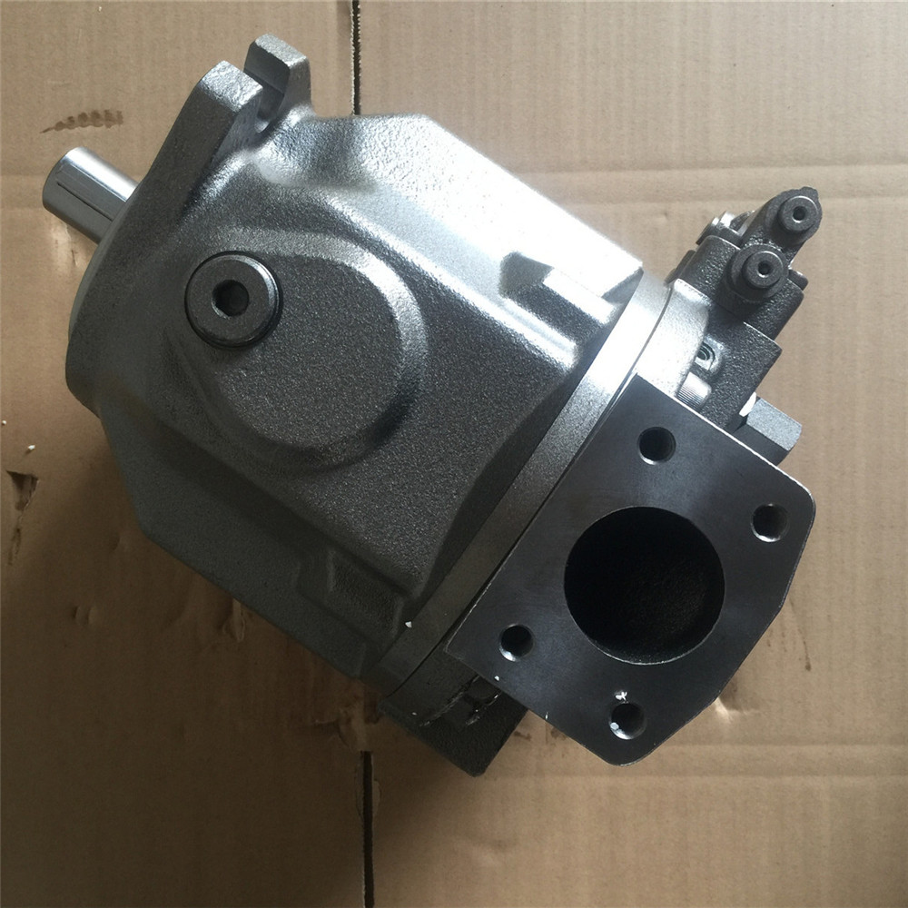
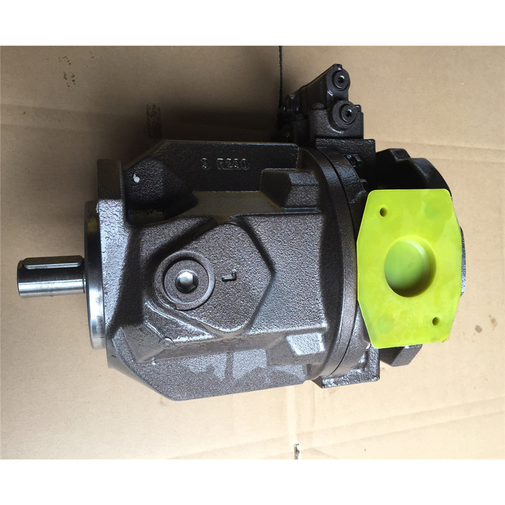
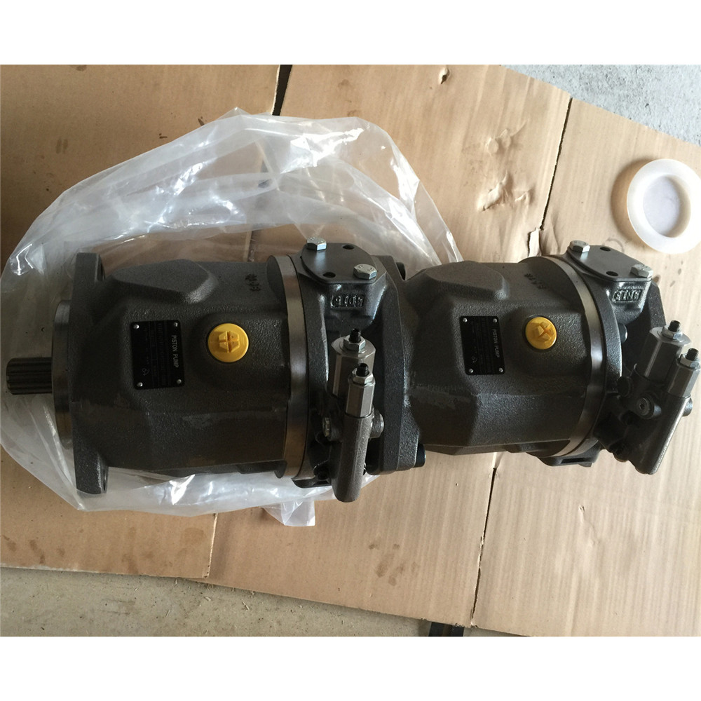
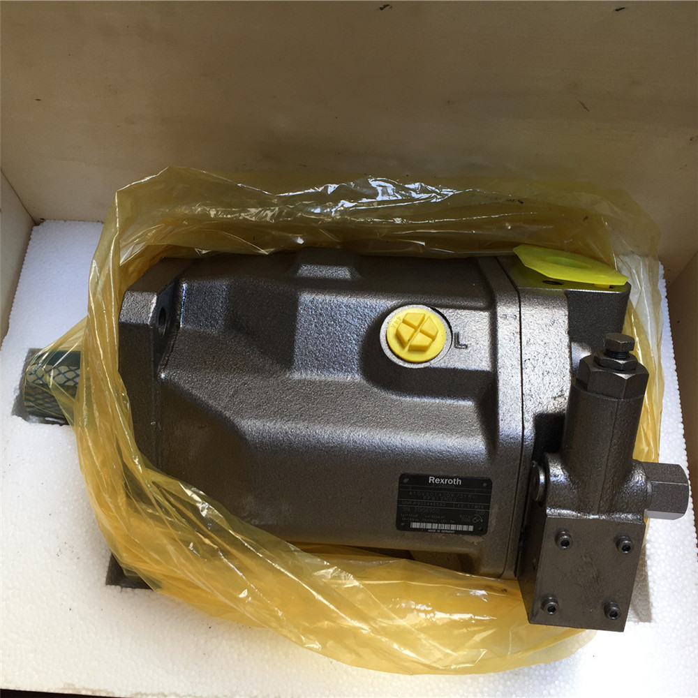
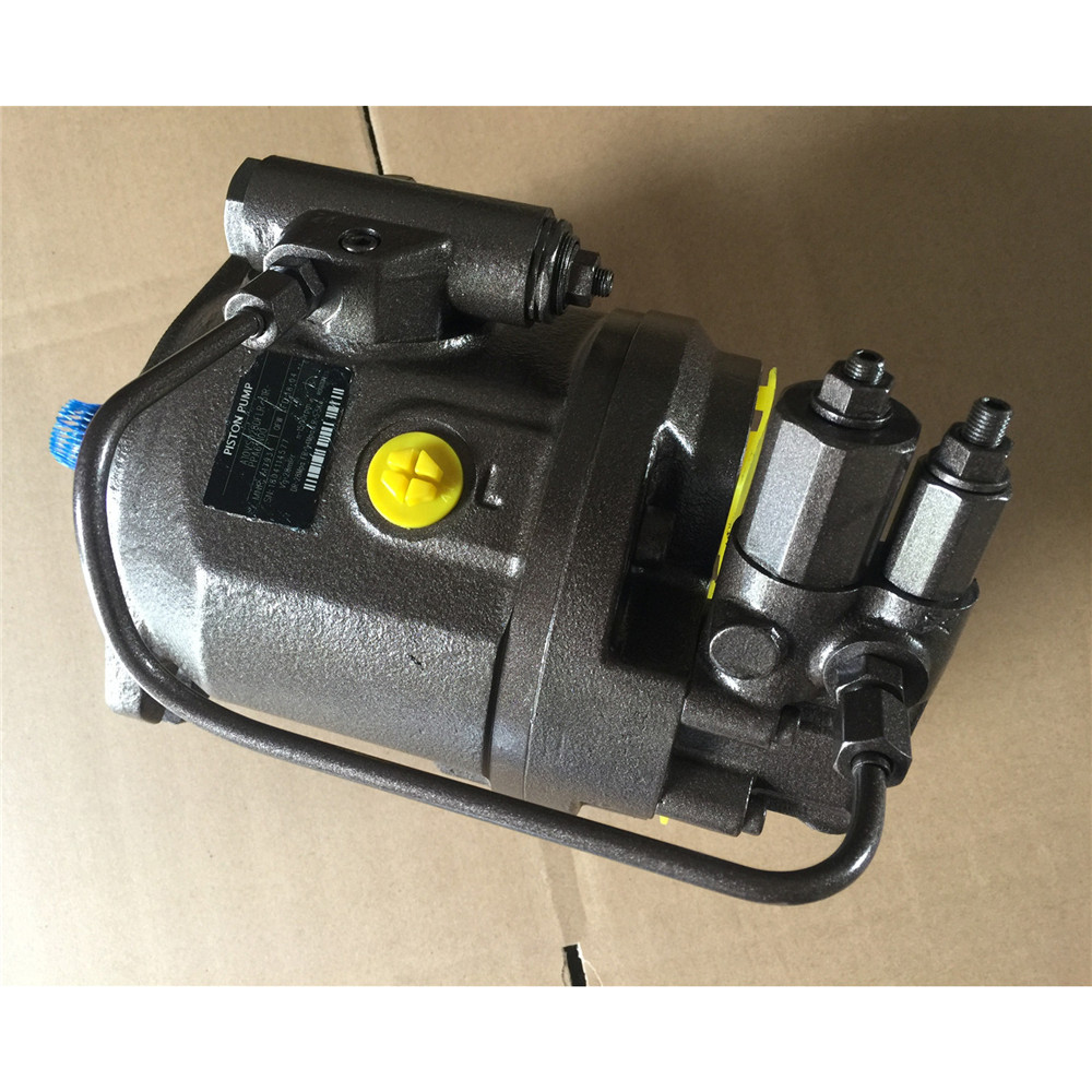
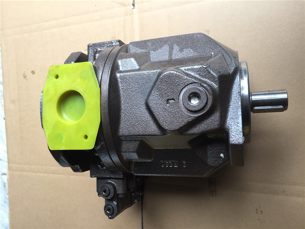
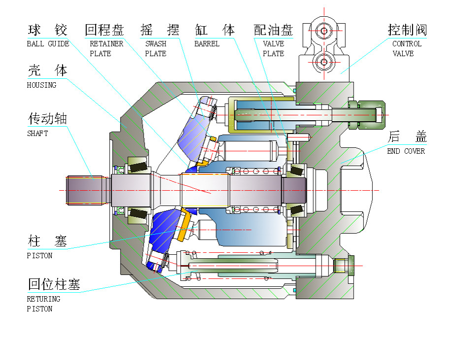
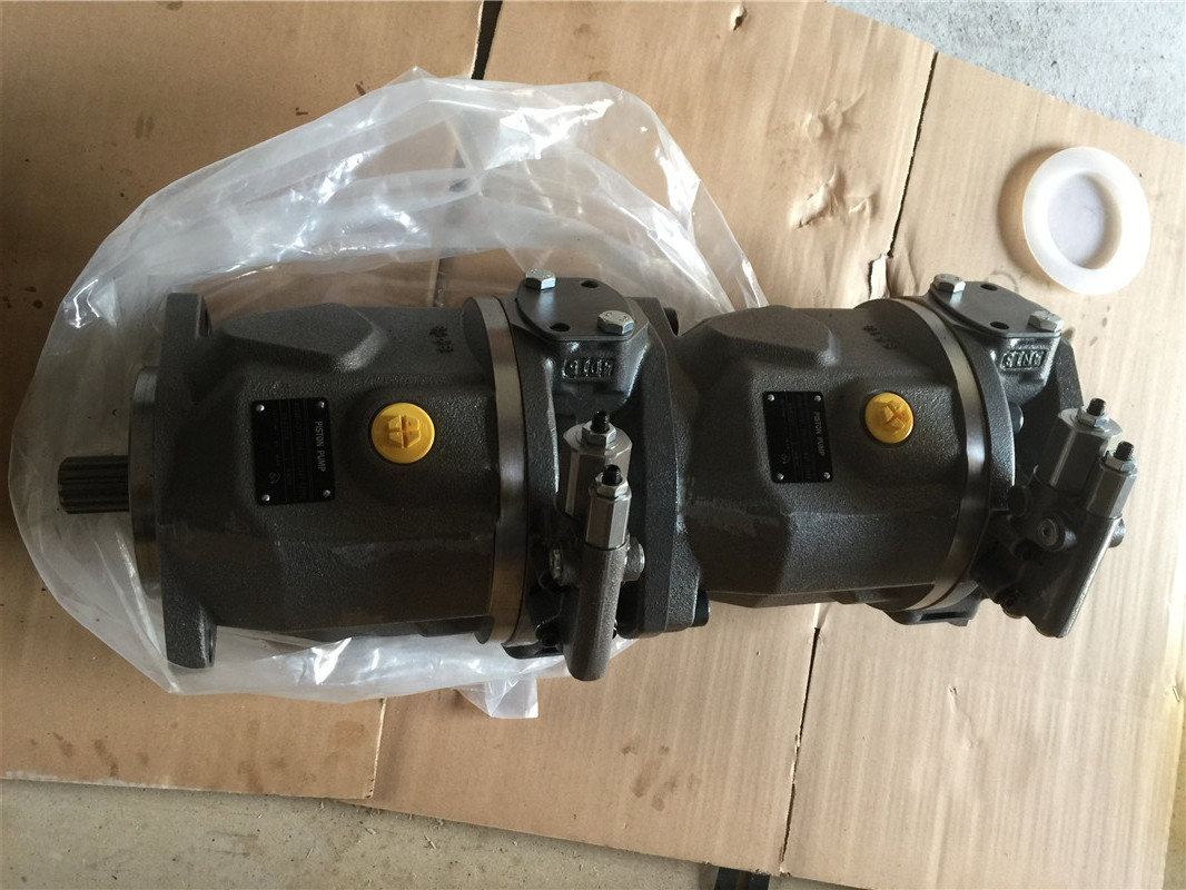
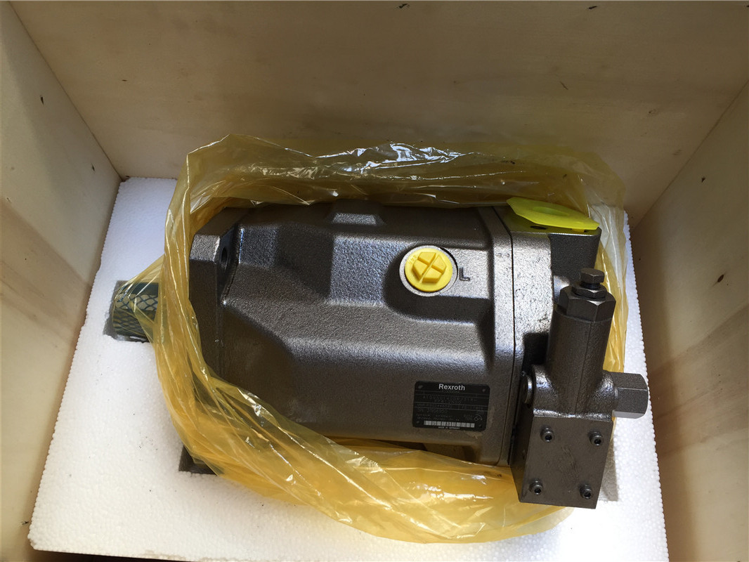
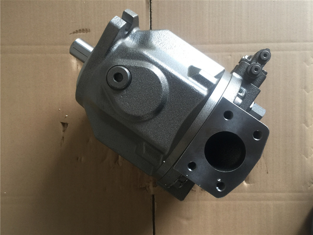
A10VSO Piston Pumps
04
7 Jan 2019
• Swash plate design axial variable piston pump used in open circuit.
• Continuous work pressure can reach 280bar,The highest instantaneous work pressure can reach 350bar.
• The flow is directly proportional to the drive rotate speed and the displacement, and can make stepless variable come true by adjusting the obliquity of the swash plate.
• There are various of control type such as DR,DFR,DFLR etc. and the control response is very fast.
• Low noises level, High efficiency, High reliability and long time service life.
• Small volume, High power density.
• Excellent oil absorbency.
• Axial and radial loading of drive shaft possible
• SAE and ISO mounting flange
• Thru shaft configuration use in circuit system.
Absolute Pressure of Inlet
Pabs min-----------------------0.8 bar
Pabs max----------------------30 bar
Press of Outlet
Nominal Pressure PN-------------------280 bar
Peak Pressure-----------------------------350 bar
The Pressure of Oil Discharge to Housing
Max.pressure allowed at outlet:can higher 0.5 bar than inlet's pressure,but must lower 2 bar of the absolute pressure.
| Displacement | Vg ml/r | 18 | 28 | 45 | 71 | 100 | 140 | |
| Max.Speed | nmax rpm | 3000 | 3000 | 3000 | 3000 | 3000 | 3000 | |
| Max.Permissible Speed | 3900 | 3600 | 3100 | 2600 | 2400 | 2100 | ||
| Max. Flow | nmax | qvL/min | 59.4 | 84 | 117 | 156 | 200 | 250 |
| VE=1500r/min | 27 | 42 | 68 | 107 | 150 | 210 | ||
| Max.Power | nmax | Pmax KW | 27.7 | 39 | 55 | 73 | 93 | 118 |
| VE=1500r/min | 12.6 | 20 | 32 | 50 | 70 | 98 | ||
| Max.Torque | NM | TmaxNm | 80.1 | 125 | 200 | 316 | 445 | 625 |
| Weight | KGS | 12 | 15 | 21 | 33 | 45 | 60 | |
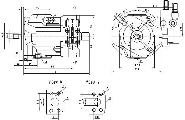
| isplacement | A1 | A3 | A4 | A5 | A6 | A7 | A8 | B1 | B2 | B4 | B5 |
| 16 | 80(82.55)h8 | 109(106.4) | 134 | 25 | 20 | M10(3/8-16UNC) | M10(3/8-16UNC) | 195 | 7(6.3) | 43 | 83 |
| 28 | 100(101.6)h8 | 140(146) | 174 | 32 | 20 | M10(7/16-14UNC) | M10(3/8-16UNC) | 206 | 9(9.5) | 40 | 90 |
| 45 | 100(101.6)h8 | 140(146) | 174 | 40 | 25 | M12(1/2-13UNC) | M10(3/8-16UNC) | 224 | 9(9.5) | 45 | 96 |
| 71 | 125(127)h8 | 180(181) | 210 | 50 | 25 | M12(1/2-13UNC) | M10(3/8-16UNC) (7/16-14UNC) | 259 | 9(12.7) | 53 | 115 |
| 100 | 125(127)h8 | 180(181) | 210 | 60 | 30 | M12(1/2-13UNC) | M14(1/2-13UNC) | 329 | 9(12.7) | 95 | 175 |
| 140 | 180h8 | 158.4x158.4 | 200x200 | 63 | 32 | M12 | M14 | 337.5 | 9 | 78 | 173 |
| isplacement | B6 | B8 | B9 | B10 | B11 | B12 | B13 | B14 | B15 | B16 | B17 | B18 | B19 | L(L1) | X |
| 16 | 11.5 | 145 | 63 | 11 | 67 | 66 | 152 | 26.2 | 52.4 | 22.2 | 47.6 | 109 | 40 | M16x1.5(9/16-18UNF) | 7/16-20UNF |
| 28 | 13 | 164 | 80 | 14 | 74 | 75 | 164 | 30.2 | 58.7 | 22.2 | 47.6 | 119 | 40 | M18x1.5(3/4-16UNF) | 7/16-20UNF |
| 45 | 13 | 184 | 90 | 14 | 83 | 81 | 184 | 35.7 | 69.9 | 26.2 | 52.4 | 129 | 40 | M22x1.5(7/8-14UNF) | 7/16-20UNF |
| 71 | 17 | 217 | 104 | 18 | 98 | 92 | 210 | 42.9 | 77.8 | 30.2 | 58.7 | 143 | 40 | M22x1.5(7/8-14UNF) | 7/16-20UNF |
| 100 | 20 | 275 | 100 | 17.5 | 106 | 95 | 236 | 50.8 | 88.9 | 31.8 | 66.7 | 148 | 40 | M27x2(1 1/16-12UNF) | 7/16-20UNF |
| 140 | 21 | 275 | 110 | 18 | 118.5 | 108 | 262 | 50.8 | 88.9 | 31.8 | 66.7 | 143 | 27 | M27x2(1 1/16-12UNF) | 7/16-20UNF |
| Displacement | A2 | B3 | B7 | A2 | B3 | B7 | ||
| 16 | U axisShaft | φ15.4(16/32DP;9T) | 31.8 | 23.8 | P axis Shaft | φ18(键6x25) | 36 | 28 |
| 28 | φ22(键6x32) | 46 | 36 | |||||
| 45 | φ22.225(16/32DP;13T) | 41 | 33.1 | φ25(键key8x36) | 52 | 42 | ||
| 71 | φ32(键key10x45) | 60 | 50 | |||||
| 100 | φ31.75(12/24DP;14T) | 55.4 | 47.5 | φ40(键key12x68) | 80 | 70 | ||
| 140 | φ45(键key14x80) | 92 | 82 | |||||
| 16 | S axis Shaft | φ19.05(16/32DP;11T) | 38 | 30 | K axis Shaft | φ15.05(键4.76x28.6) | 41 | 33 |
| 28 | φ22.225(16/32DP;Z=13T) | 41 | 33.1 | φ22.225(键6.38x28.6) | 41.3 | 33.3 | ||
| 45 | φ25.4(16/32DP;15T) | 45.9 | 38 | φ25.4(键key6.38x35) | 45.9 | 38.1 | ||
| 71 | φ31.75(12/24DP;14T) | 55.4 | 47.5 | φ31.75(键key7.94x41.3) | 55.4 | 47.5 | ||
| 100 | φ38.1(12/24DP;17T) | 61.9 | 54 | φ38.1(键key9.52x50) | 61.9 | 54 | ||
| 140 | φ44.45(8/16 DP;13T) | 75 | 67 |
Note: The dimension which is in front of parentheses A1、A3、B2 is as ISO 2 hole A mounting flange dimension and inside of parentheses is SAE 2 hole C mounting flange dimension; The dimension which is in front of parentheses A7、A8、L(L1)is metric screws thread, inner parentheses dimension is UNC screws thread.
04
7 Jan 2019
DFR / DFR1- PRESSURE FLOW CONTROL
DFR control provides a pressure control function along with the means to control pump flow by varrying a
differential pressure accross an orifice (fixed orifice, adjustable flow control,directional control). The pump
supplies only the amount of system flow as controlled by the adjustable orifice.
In the DFR1 control the orifice between the X port and tank is plugged
Setting range: 290 PSI (20 bar) ~ 4000 PSI (280 bar)
DFLR -PRESSURE / FLOW / POWER CONTROL
DFR control provides a pressure control function along with the means to control pump flow by varrying a differential pressure accross an orifice (fixed orifice, adjustable flow control,directional control). The pump supplies only the amount of system flow as controlled by the adjustable orifice.
In the DFR1 control the orifice between the X port and tank is Plugged.
Setting range: 290 PSI (20 bar) ~ 4000 PSI (280 bar)
04
7 Jan 2019
DR - PRESSURE CONTROL
DR pressure control maintains a constant system pressure at the outlet of the pump. The pump supplies flow until the the preset adjustment pressure setting is reached. Pressure setting may be steplessly set at the
pilot valve.
Setting range: 290 PSI (20 bar) ~ 4000 PSI (280 bar)
DRG - PRESSURE CONTROL REMOTE
DRG pressure control function and design are the same as DR control with the added feature of remote adjustment of the control pressure with the use of an external relief valve.
External relief is connected to the X port on the pressure control and the differential pressure at the control spool is set as standard to 290 PSI (20 bar) pilot flow will be .4 gpm (1.5 L/min).
Setting range: 290 PSI (20 bar) ~ 4000 PSI (280 bar)
DG - TWO POINT, DIRECT CONTROL
DG pressure control allows pump flow to be switched from maximum flow to minumum flow by supplying an external pilot switching pressure at port X.
Pump can only be switched between maximum & minimum flow , a minimum pilot pressure of 725 PSI is required. The actual switching pilot pressure required will be dependent on the system operating pressure at the outlet of the pump.
FILL PUMP CASING:
Before starting,fill pump case with clean system fluid through uper most drain port. Pipework must be installed in such a way to ensure that the case is always full of oil during operation.
STARTING:
During initial starting it may be necessary to bleed air from outlet. IFP air bleed valves ABT20S is available for this purpose.
SYSTEM RELIEF VALVE:
Although A10VSO series pumps have compensator controls to limit maximum pressure, a system relief adjusted 200 PSI higher than compensator pressure is recommended for safety considerations.